Description
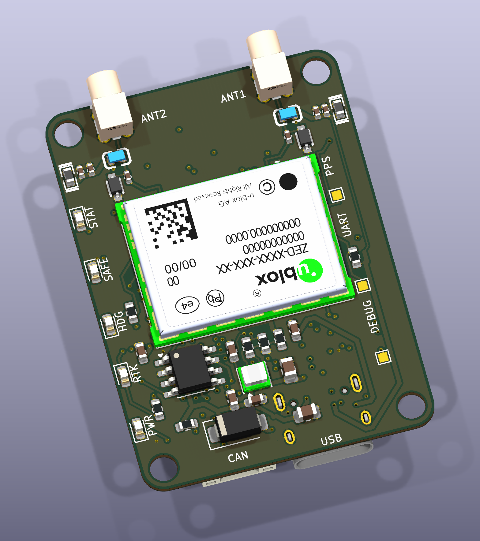
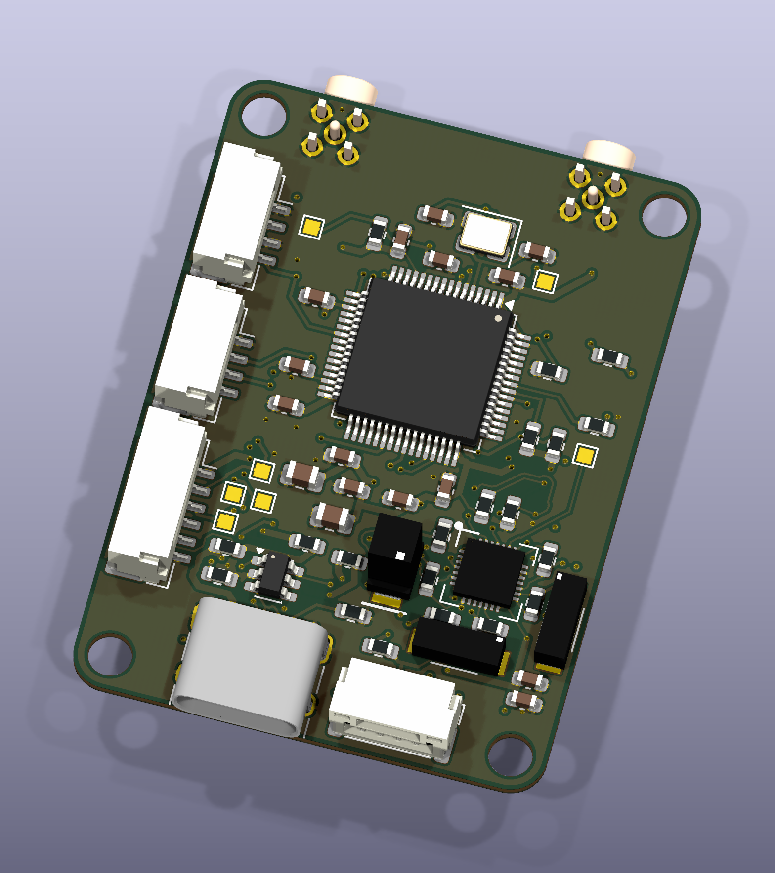
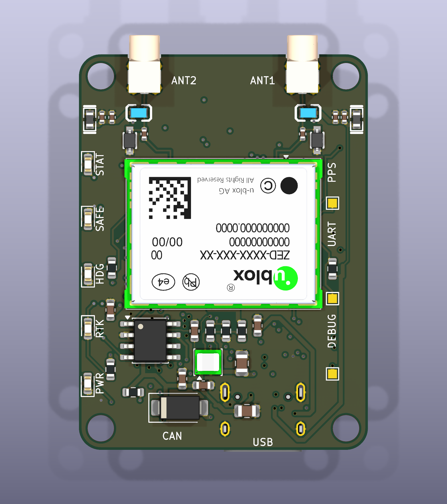
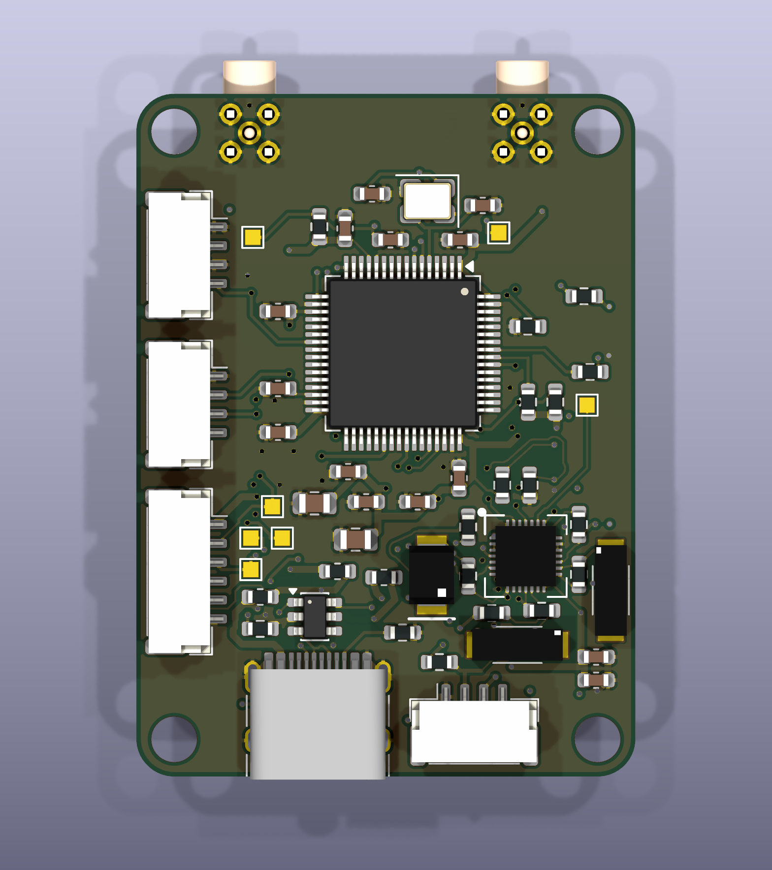
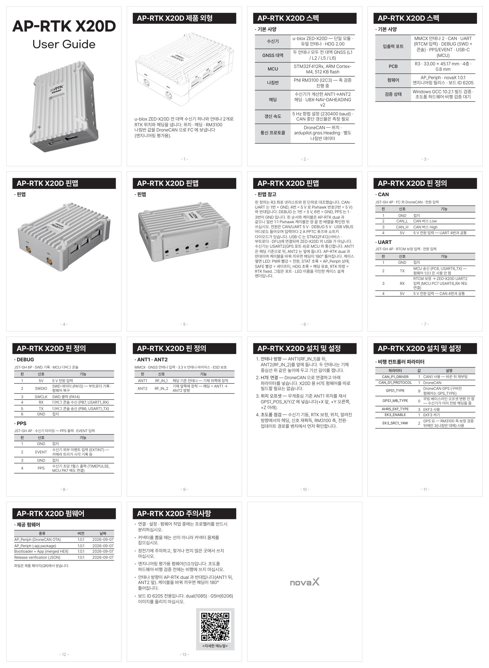
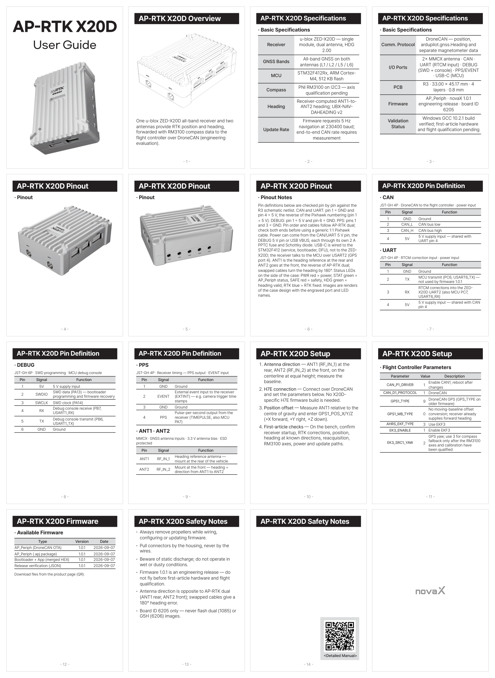
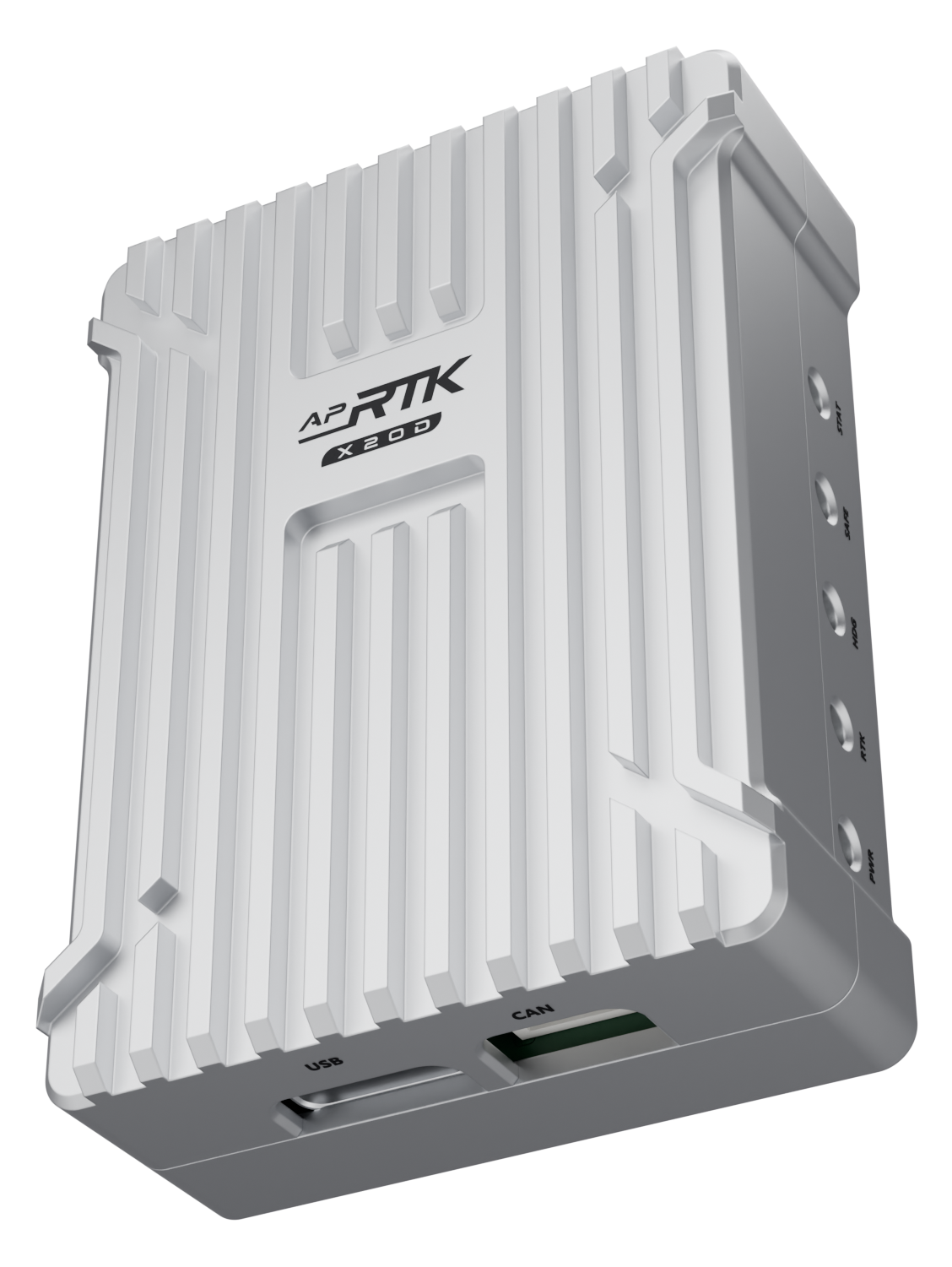
AP-RTK X20D uses one u-blox ZED-X20D all-band receiver and two antennas for RTK positioning and heading. The STM32 forwards the receiver's position and heading plus separate RM3100 compass measurements over DroneCAN to the flight controller; yaw fusion belongs to the flight controller, not the peripheral MCU. Product images are renders of the enclosure design fitted with the R3 PCB, with engraved port and LED names; the gallery also shows the R3 PCB CAD renders. Firmware 1.0.1 is supplied for engineering evaluation, not as production or flight-qualified firmware.
Basic Specifications
Receiver
u-blox ZED-X20D — single module, dual antenna, HDG 2.00
GNSS Bands
All-band GNSS on both antennas (L1 / L2 / L5 / L6)
MCU
STM32F412Rx, ARM Cortex-M4, 512 KB flash
Compass
PNI RM3100 on I2C3 — axis qualification pending
Heading
Receiver-computed ANT1-to-ANT2 heading; UBX-NAV-DAHEADING v2
Update Rate
Firmware requests 5 Hz navigation at 230400 baud; end-to-end CAN rate requires measurement
Comm. Protocol
DroneCAN — position, ardupilot.gnss.Heading and separate magnetometer data
I/O Ports
2× MMCX antenna · CAN · UART (RTCM input) · DEBUG (SWD + console) · PPS/EVENT · USB-C (MCU)
PCB
R3 · 33.00 × 45.17 mm · 4 layers · 0.8 mm
Firmware
AP_Periph · novaX 1.0.1 engineering release · board ID 6205
Validation Status
Windows GCC 10.2.1 build verified; first-article hardware and flight qualification pending
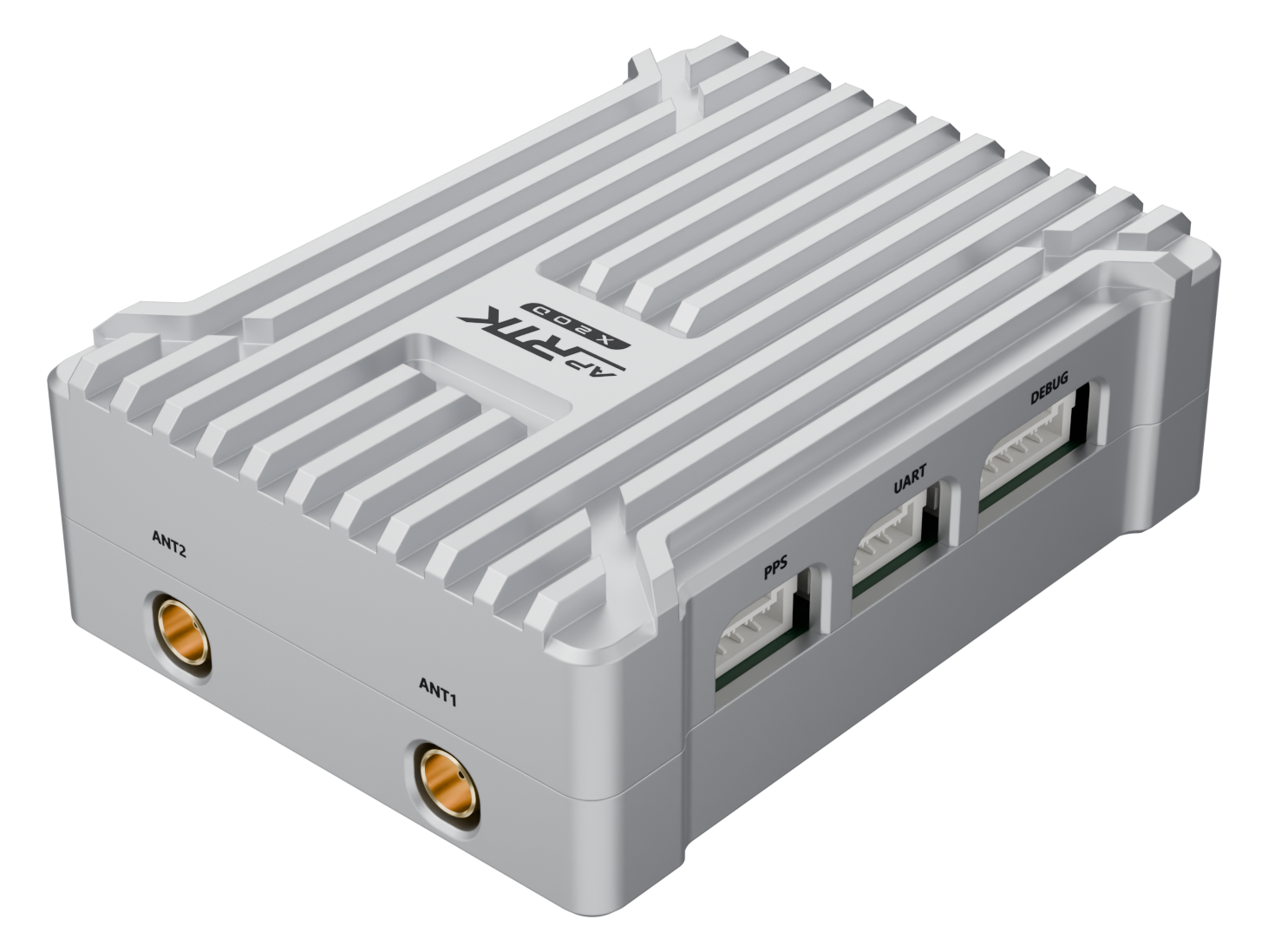
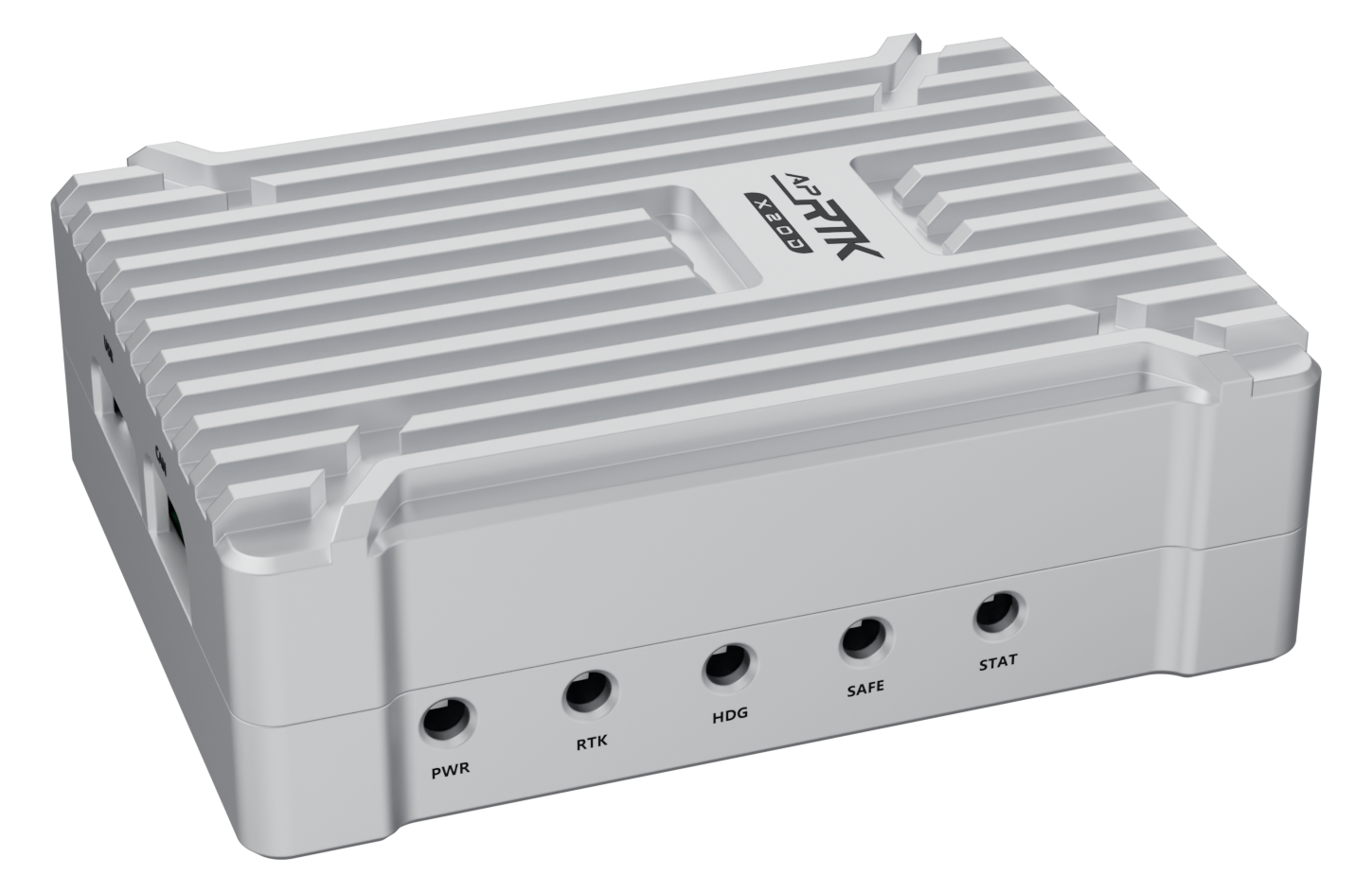
Pin definitions below are checked pin by pin against the R3 schematic netlist. CAN and UART: pin 1 = GND and pin 4 = 5 V, the reverse of the Pixhawk numbering (pin 1 = 5 V). DEBUG: pin 1 = 5 V and pin 6 = GND. PPS: pins 1 and 3 = GND. Pin order and cables follow AP-RTK dual; check both ends before using a generic 1:1 Pixhawk cable. Power can come from the CAN/UART 5 V pin, the DEBUG 5 V pin or USB VBUS, each through its own 2 A PPTC fuse and Schottky diode. USB-C is wired to the STM32F412 (service, bootloader, DFU), not to the ZED-X20D; the receiver talks to the MCU over USART2 (GPS port 4). ANT1 is the heading reference at the rear and ANT2 goes at the front, the reverse of AP-RTK dual; swapped cables turn the heading by 180°. Status LEDs on the side of the case: PWR red = power, STAT green = AP_Periph status, SAFE red = safety, HDG green = heading valid, RTK blue = RTK fixed. Images are renders of the case design with the engraved port and LED names.
| Pin | Signal | Function |
|---|---|---|
| CAN · JST-GH 4P · DroneCAN to the flight controller · power input | ||
| 1 | GND | Ground |
| 2 | CAN_L | CAN bus low |
| 3 | CAN_H | CAN bus high |
| 4 | 5V | 5 V supply input — shared with UART pin 4 |
| UART · JST-GH 4P · RTCM correction input · power input | ||
| 1 | GND | Ground |
| 2 | TX | MCU transmit (PC6, USART6_TX) — not used by firmware 1.0.1 |
| 3 | RX | RTCM corrections into the ZED-X20D UART2 (also MCU PC7, USART6_RX) |
| 4 | 5V | 5 V supply input — shared with CAN pin 4 |
| DEBUG · JST-GH 6P · SWD programming · MCU debug console | ||
| 1 | 5V | 5 V supply input |
| 2 | SWDIO | SWD data (PA13) — bootloader programming and firmware recovery |
| 3 | SWCLK | SWD clock (PA14) |
| 4 | RX | Debug console receive (PB7, USART1_RX) |
| 5 | TX | Debug console transmit (PB6, USART1_TX) |
| 6 | GND | Ground |
| PPS · JST-GH 4P · Receiver timing — PPS output · EVENT input | ||
| 1 | GND | Ground |
| 2 | EVENT | External event input to the receiver (EXTINT) — e.g. camera trigger time stamps |
| 3 | GND | Ground |
| 4 | PPS | Pulse-per-second output from the receiver (TIMEPULSE, also MCU PA7) |
| ANT1 · ANT2 · MMCX · GNSS antenna inputs · 3.3 V antenna bias · ESD protected | ||
| ANT1 | RF_IN_1 | Heading reference antenna — mount at the rear of the vehicle |
| ANT2 | RF_IN_2 | Mount at the front — heading = direction from ANT1 to ANT2 |
| Type | Version | Date | Size | Download |
|---|---|---|---|---|
AP_Periph (DroneCAN OTA) Application binary for DroneCAN OTA. Bench update and recovery qualification is pending. | 1.0.1 | 2026-09-07 | 196 KB | AP-RTK_X20D-v1.0.1.bin SHA-256: d83dacf71278302587b3fc6e42c9c7e2d5eeab3d308bc7dc85302b4e9407f452 |
AP_Periph (.apj package) Board ID 6205 application package for ArduPilot-compatible uploaders over the MCU USB bootloader. Not offered in this catalog's Web Updater. | 1.0.1 | 2026-09-07 | 197 KB | AP-RTK_X20D-v1.0.1.apj SHA-256: e896e08ee87b92bc930ebd737ad5196fe2973cf6ef569962d2d067d2c94d21e0 |
Bootloader + App (merged HEX) First-article SWD / STM32 ROM USB DFU image at 0x08000000. Raw DFU/SWD does not enforce board ID; verify X20D R3 hardware before programming. | 1.0.1 | 2026-09-07 | 714 KB | AP-RTK_X20D-v1.0.1_with_bl.hex SHA-256: 2c843e66707e2843c5364f9f82a821954192b20ba6020b3f252d686b97733b36 |
Release verification (JSON) File sizes and SHA-256 hashes, committed source and patch validation, binary/HEX consistency and Windows build tool provenance. Not a flashable image. | 1.0.1 | 2026-09-07 | 3 KB | AP-RTK_X20D-v1.0.1-verification.json SHA-256: a2f054d1672cd6afc6fc220d10d97b8a3e8b9735e764ee4c6daa8bc4a12311eb |
v1.0.1 is an engineering release, not hardware/flight approval. Native Windows GCC 10.2.1 build (Cygwin, no WSL). Product firmware string: novaX AP-RTK X20D v1.0.1; upstream AP_Periph numeric version remains 1.8.0-dev, so DroneCAN GetNodeInfo major/minor can show 1.8. Board ID 6205; never substitute dual (1085) or G5H (6206) images. Raw DFU/SWD does not enforce board ID. Downloads are available here without access to the private GNSS source repository. Live GNSS, heading, compass axes and USB/DFU/CAN update/recovery still need first-article testing. The catalog Web Updater is not enabled for this unqualified target.
| Parameter | Value | Description |
|---|---|---|
| AF-H7E flight controller — DroneCAN and EKF3 | ||
CAN_P1_DRIVER | 1 | Enable CAN1; reboot after changes |
CAN_D1_PROTOCOL | 1 | DroneCAN |
GPS1_TYPE | 9 | DroneCAN GPS (GPS_TYPE on older firmware) |
GPS1_MB_TYPE | 0 | No moving-baseline offset conversion; receiver already supplies forward heading |
AHRS_EKF_TYPE | 3 | Use EKF3 |
EK3_ENABLE | 1 | Enable EKF3 |
EK3_SRC1_YAW | 2 | GPS yaw; use 3 for compass fallback only after the RM3100 axes and calibration have been qualified |
1. Antenna direction — ANT1 / RF_IN_1 at the rear; ANT2 / RF_IN_2 at the front. The receiver reports the ANT1-to-ANT2 vector, so the firmware sets CFG-NAVSPG-DAHEADING_OFFSET to 0. Keep antennas on the centerline at equal height and measure the baseline. This direction is opposite to the AP-RTK dual artwork; swapping cables produces a 180° heading error. 2. H7E connection — Use DroneCAN and the flight-controller parameters above. X20D needs only its AP_Periph image; no X20D-specific H7E firmware rebuild is required. Do not copy G5H GPS1_MB_* offsets onto this node. 3. Position offset — Measure ANT1 relative to the vehicle center of gravity and enter GPS1_POS_X/Y/Z on H7E (+X forward, +Y right, +Z down). Do not reuse example offsets without measurement. 4. First-article checks — Confirm factory receiver startup, RTK corrections, live position, yaw at known headings, loss/reacquisition, RM3100 axes, power and all update/recovery paths on a bench before any flight use. 5. Receiver reference — u-blox ZED-X20D official product information: https://www.u-blox.com/en/product/zed-x20d-module