Description
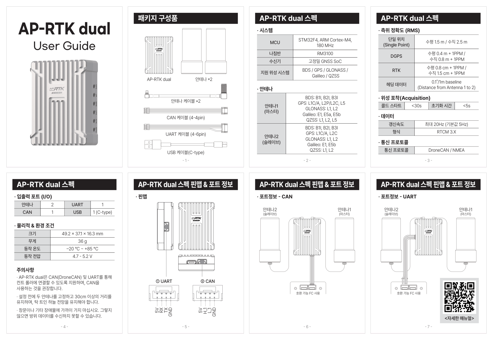
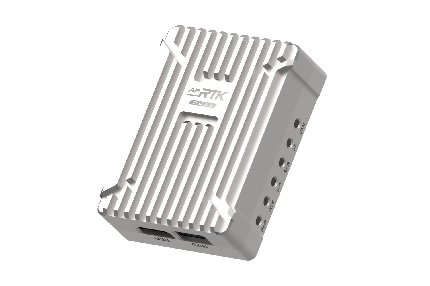
AP-RTK dual is a high-precision dual-antenna RTK GNSS receiver built on an STM32F4 processor. Centimeter-level positioning and dual-antenna heading make it ideal for survey-grade autonomous platforms and applications that demand reliable yaw determination independent of magnetic interference.
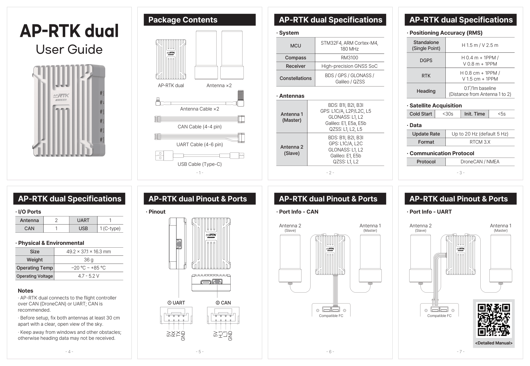
Basic Specifications
MCU
STM32F4, ARM Cortex-M4, 180 MHz
Compass
RM3100
Receiver
High-precision GNSS SoC
Satellite Systems
BDS / GPS / GLONASS / Galileo / QZSS
Antenna 1 (Master)
BDS B1I/B2I/B3I · GPS L1C/A/L2/L5 · GLONASS L1/L2 · Galileo E1/E5a/E5b · QZSS L1/L2/L5
Antenna 2 (Slave)
BDS B1I/B2I/B3I · GPS L1C/A/L2C · GLONASS L1/L2 · Galileo E1/E5b · QZSS L1/L2
Single-Point Accuracy
H 1.5 m / V 2.5 m (RMS)
DGPS Accuracy
H 0.4 m + 1PPM / V 0.8 m + 1PPM
RTK Accuracy
H 0.8 cm + 1PPM / V 1.5 cm + 1PPM
Cold Start
< 30 sec
Hot Start
< 5 sec
Update Rate
Max. 20 Hz (Default 5 Hz)
Data Format
RTCM 3.X
Comm. Protocol
DroneCAN / NMEA
I/O Ports
2× Antenna · 1× CAN · 1× UART · 1× USB-C
Size
49.2 × 37.1 × 16.3 mm
Weight
36 g
Operating Temp
-20 ~ +85 ℃
Operating Voltage
4.7 – 5.2 V
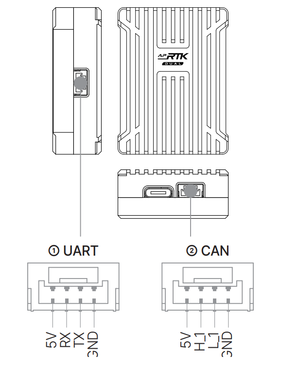
① UART (5V · RX · TX · GND) · ② CAN (5V · CAN_H · CAN_L · GND).
| Type | Version | Date | Size | Download |
|---|---|---|---|---|
AP_Periph (DroneCAN OTA) Update over DroneCAN: Mission Planner → Optional Hardware → DroneCAN → select node → Update. No cable change needed. | 0.1.0 | 2026-06-04 | 157 KB | AP-RTK_dual-v0.1.0.bin SHA-256: d77268b9d9bb3638eea0749cc5a937a11394d00d20b9dd57ee99df2f1f4c4e74 |
AP_Periph (.apj package) ArduPilot firmware package — upload via Mission Planner over the USB-C bootloader, or update over DroneCAN (OTA above). Not flashable from the catalog Web Updater (this is a DroneCAN peripheral, not a USB-serial/DFU device). | 0.1.0 | 2026-06-04 | 157 KB | AP-RTK_dual-v0.1.0.apj SHA-256: 886c19a1bb251f0168bca72744c26f743261d3fcb6262488513226e785df4ac3 |
Bootloader + App (merged HEX · SWD) Bootloader + application combined image based at 0x08000000. SWD/ST-Link only (e.g. STM32CubeProgrammer) for factory bring-up or recovery on a blank MCU — this DroneCAN peripheral has no USB DFU, so it is not offered in the Web Updater. For routine updates use the DroneCAN OTA or .apj methods above. | 0.1.0 | 2026-06-04 | 608 KB | AP-RTK_dual-v0.1.0_with_bl.hex SHA-256: 1ed5a9af0044ba585978ddb4cde3eabe7f45b78504d61313967ad5463ad96f7a |
Downloads below are hosted in this catalog under /firmware/gnss/. Existing released firmware bytes and SHA-256 checksums are unchanged.
| Parameter | Value | Description |
|---|---|---|
| DroneCAN connection & heading | ||
CAN_P1_DRIVER | 1 | Enable the autopilot (H7E) CAN1 port (reboot required after change) |
CAN_D1_PROTOCOL | 1 | DroneCAN protocol on the CAN1 driver |
GPS1_TYPE | 9 | DroneCAN GPS. On firmware older than 4.6 the parameter is GPS_TYPE = 9 |
GPS_AUTO_CONFIG | 2 | Automatically configure the DroneCAN GPS |
GPS1_MB_TYPE | 1 | Enable dual-antenna moving baseline (unlocks the offsets below). Pre-4.6: GPS_MB1_TYPE = 1 |
GPS1_MB_OFS_X | 0.50 | Master(ANT1) is 0.50 m in front of Slave(ANT2) → +0.50 (positive = Master in front). Set to your measured separation. Pre-4.6: GPS_MB1_OFS_X |
GPS1_MB_OFS_Y | 0 | 0 on the centerline (positive = Master to the right of Slave). Pre-4.6: GPS_MB1_OFS_Y |
GPS1_MB_OFS_Z | 0 | 0 at equal height (positive = Master below Slave). Pre-4.6: GPS_MB1_OFS_Z |
EK3_SRC1_YAW | 3 | GPS yaw with compass fallback (use 2 for GPS-only yaw) |
AHRS_EKF_TYPE | 3 | Heading works only when AHRS uses EKF3 |
EK3_ENABLE | 1 | Enable EKF3 |
| Position offset · Master antenna → vehicle CoG (example — measure on your airframe) | ||
GPS1_POS_X | 0.25 | Master antenna fore/aft offset from the center of gravity in meters (positive = in front of CoG). Example: with the CoG at the midpoint of the 500 mm baseline, the front Master antenna is half the baseline ahead → +0.25 m. Pre-4.6: GPS_POS1_X |
GPS1_POS_Y | 0.00 | Lateral offset (positive = to the right of CoG). Example: the Master antenna sits on the airframe centerline (Figure 1), so 0. Pre-4.6: GPS_POS1_Y |
GPS1_POS_Z | -0.10 | Vertical offset (positive = below CoG). Example: the antenna is mounted 0.10 m above the CoG → −0.10 m. Pre-4.6: GPS_POS1_Z |
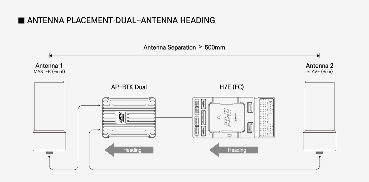
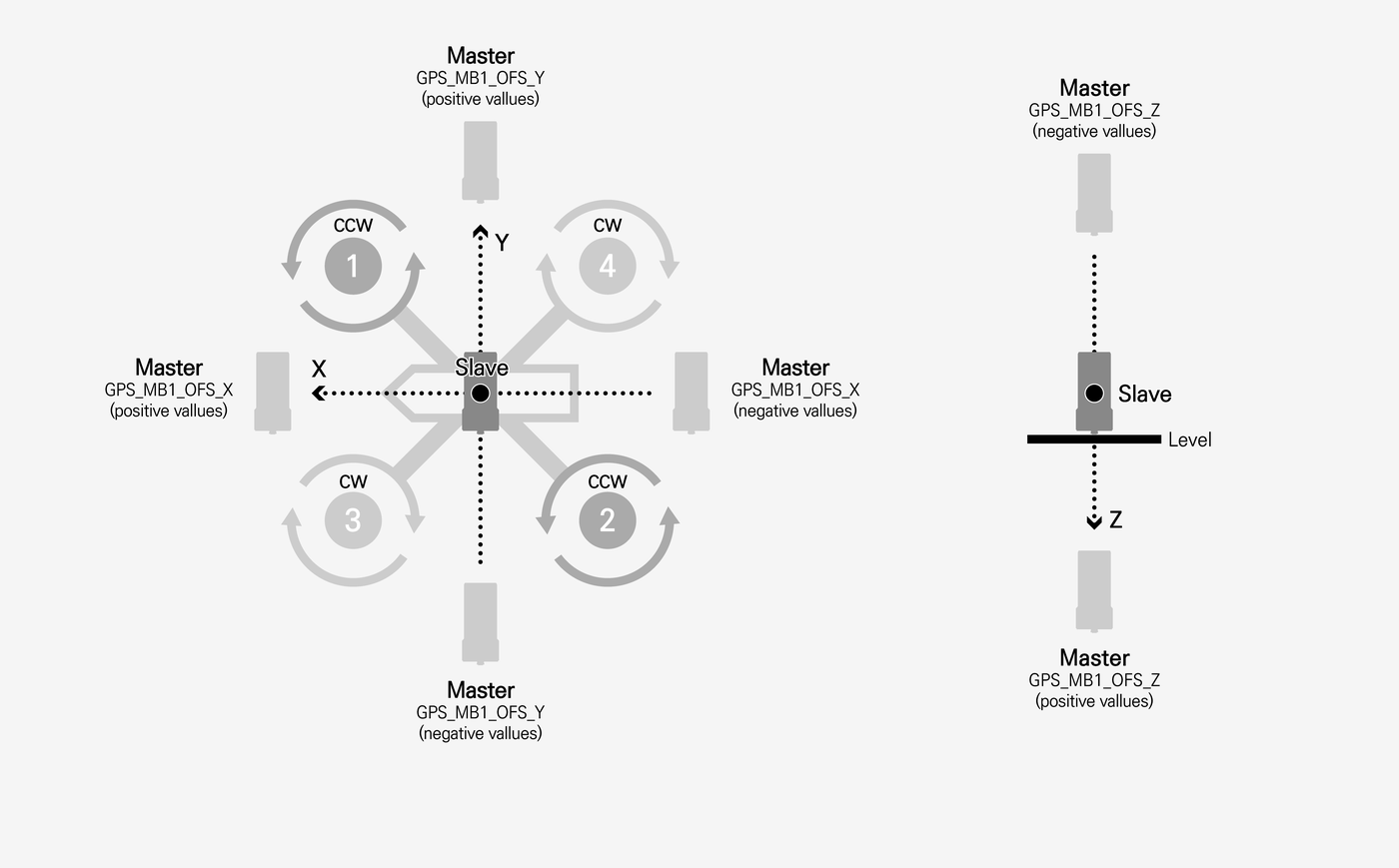
Recommended layout (Figure 1): ANT1 Master at the front, ANT2 Slave at the rear, both on the airframe centerline at equal height, with the baseline parallel to the flight direction (heading). The example below uses a 500 mm (0.50 m) separation. Parameter names follow ArduPilot 4.6+ (GPS1_…); the equivalent pre-4.6 names are noted in each row. 1. Wiring — Connect the module's CAN port to the autopilot (H7E) CAN1 port with the supplied cable, as shown in Figure 1. The module is powered from the same connector (4.7–5.2 V). 2. Antenna mounting — Following Figure 1, mount ANT1 (Master) toward the nose and ANT2 (Slave) toward the tail on the centerline. Keep at least 500 mm between antennas at equal height with a clear, unobstructed sky view (avoid windows and obstructions). A longer baseline gives a more accurate heading. 3. Offset parameters — Offsets run from the Slave to the Master antenna in body frame: +X = Master in front, +Y = Master to the right, +Z = Master below the Slave (see Figure 2 for the sign convention). For the recommended layout: GPS1_MB_OFS_X = 0.50, GPS1_MB_OFS_Y = 0, GPS1_MB_OFS_Z = 0. Set GPS1_MB_OFS_X to the separation you actually measured (in meters), then reboot the autopilot. 4. Heading check — In Mission Planner's flight data screen watch the gpsyaw value: rotate the airframe and confirm the reported heading follows. The onboard RM3100 compass is detected automatically over DroneCAN and serves as fallback (EK3_SRC1_YAW = 3). 5. RTK corrections — Inject RTCM corrections from an RTK base station or an NTRIP (CORS) service via the ground station. Wait for the GPS status to reach RTK Fixed for centimeter-level positioning. 6. Antenna position offset (Position offset table) — Measure the Master (ANT1) antenna position relative to the vehicle's center of gravity and enter it in GPS1_POS_X/Y/Z (pre-4.6: GPS_POS1_X/Y/Z): +X forward, +Y right, +Z below the CoG. The table values (0.25 / 0.00 / −0.10) are only an example for the Figure 1 layout — Master on the centerline, 0.25 m (half the 500 mm baseline) ahead of a CoG at the baseline midpoint, antenna 0.10 m above it — so measure your own airframe. This improves position accuracy and is independent of the heading offsets in step 3.