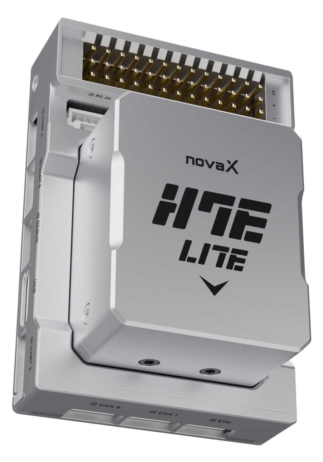
Description
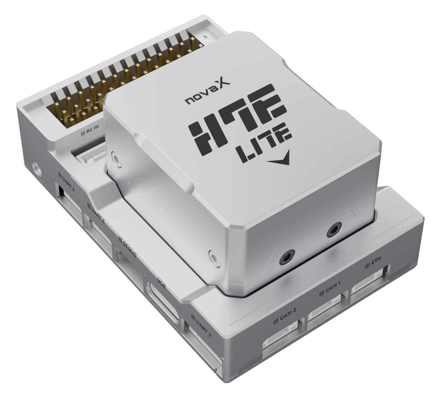
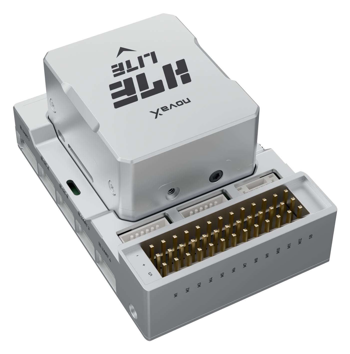
AF-H7E Lite keeps the AF-H7E STM32H753 compute module and sensor module on a compact carrier without the IO co-processor. All 12 PWM outputs and an SBUS output come straight from the flight-controller MCU, with dual CAN, 100 Mbps Ethernet, redundant power inputs and a 5-pin RC input that takes AF-H7E cables. In development - the pin definition may change before release.
Basic Specifications
MCU
STM32H753, ARM Cortex-M7, 480 MHz
RAM / Flash
1 MB / 2 MB
IMU
ICM-42688-P, BMI088
Secondary IMU
ICM-20649 (optional)
Magnetometer
RM3100 (optional; use an external compass when not fitted)
Barometer
2× ICP-20100
Operating Voltage
4.75 – 5.7 V (Rated 5 V)
USB Input
4.75 – 5.25 V
Power Input
POWER 1 + POWER 2 (redundant, I2C power modules)
PWM Output
12 FMU channels (DShot except M7–M8) + SBUS out
RC Input
S.Bus, PPM, DSM / Spektrum (with DSM bind)
RSSI Input
Analog
UART
6 serial ports (2 with flow control) + debug console
I²C
2 ports (I2C A, I2C B) + power-module bus on POWER 1 · 2
CAN
2 Port
Ethernet
100 Mbps x 1 Port
Size
43.0 × 63.4 × 29.2 mm (concept case)
Supported F/W
novaX ArduPilot (Copter and Plane releases)
Click any image to open full size
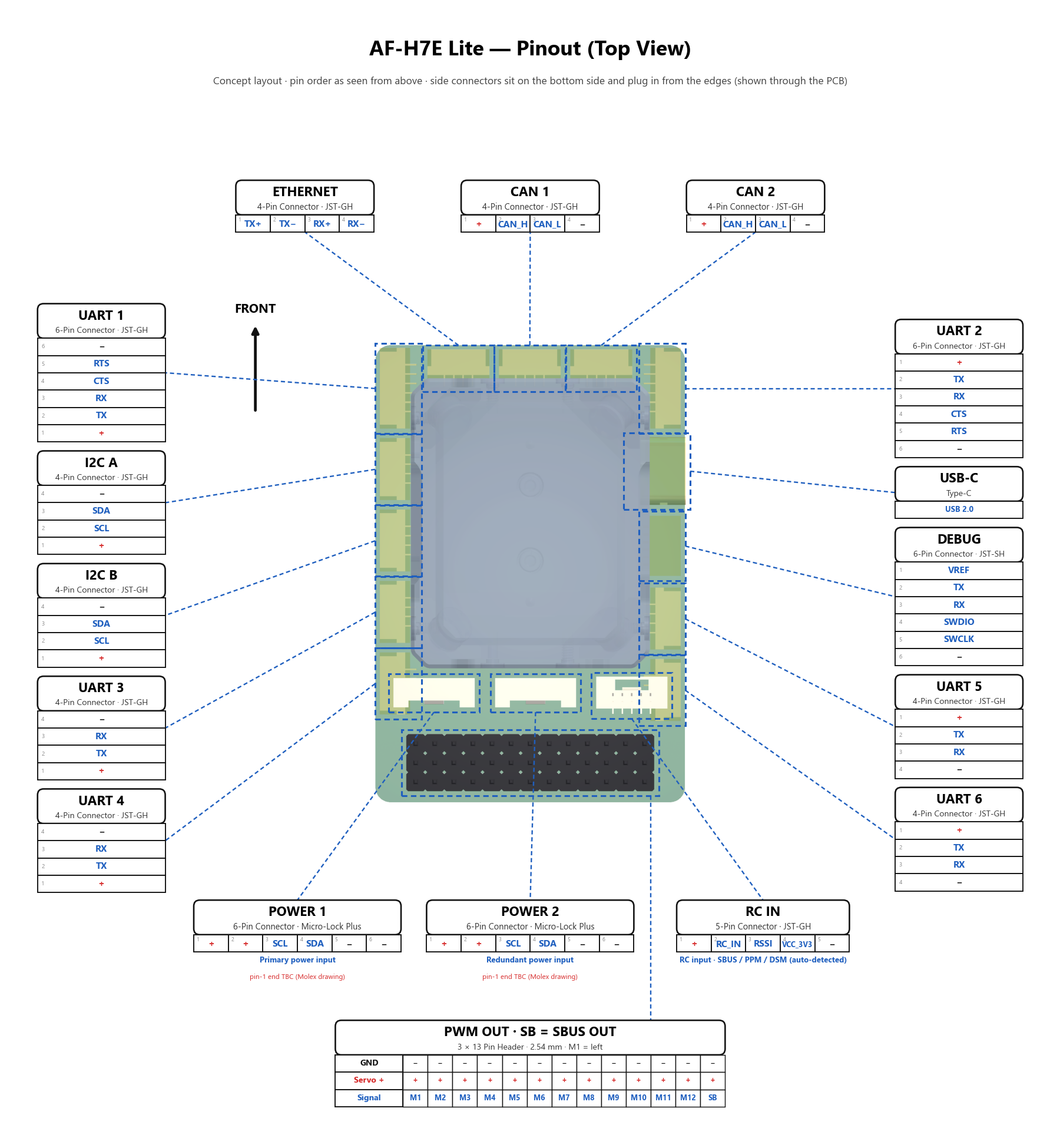
Preliminary pin definition — AF-H7E Lite is in development and connectors may change before release. On every JST connector pin 1 is the supply pin and the last pin is GND, following the Pixhawk connector standard. UART n maps to ArduPilot SERIALn: UART 1–2 default to MAVLink telemetry and UART 3–4 default to GPS. GPS modules connect to any UART or over DroneCAN; there is no dedicated GPS/safety port and no safety switch. RC IN is a 5-pin connector with the same pinout as AF-H7E and takes an SBUS, PPM or DSM receiver directly on pin 2 (protocol auto-detected, wired to the flight-controller MCU, no IO board needed); pin 1 supplies 5 V and pin 4 a switched 3.3 V for DSM / Spektrum satellite receivers, which the flight controller power-cycles to bind them. On-board without a connector: microSD card slot (logging), buzzer and RGB status LED. The + rail of the PWM header is not powered by the flight controller. The 13th header column, SB, is an SBUS output, not a PWM channel: it carries servo channels 1–16 on one wire from USART6 (SERIAL8) with the signal inversion done inside the STM32H7, so SBUS servos, SBUS-to-PWM decoders and gimbals plug in with a standard servo lead and take power from the servo rail. Outputs share rate and protocol within the timer groups M1–M4, M5 · M6 · M9 · M10, M7–M8 and M11–M12; DShot works on every group except M7–M8, whose timer has no DMA (PWM and OneShot only). As on AF-H7E, the PWM signal row (S) is the rearmost row: the case has a keyed comb behind it so servo plugs only fit with S at the rear, and a wall separates POWER 1 · POWER 2 · RC IN from the PWM header. The pinout image is a top view of the concept carrier: side connectors are mounted on the bottom side and plug in from the edges, and each table lists pins in the order they sit when seen from above. POWER 1 and POWER 2 use the same Molex Micro-Lock Plus connector as AF-H7E; their pin-1 end is still to be confirmed. POWER 1 and POWER 2 take I2C (INA2xx) power modules; a DroneCAN power module (for example 14S / 200 A) reports over CAN 1 or CAN 2 (BATT_MONITOR 8) and needs a split cable that feeds its 5 V into POWER 1, because the CAN connectors supply 5 V rather than accept it.
| Pin | Signal | Function |
|---|---|---|
| POWER 1 · Molex Micro-Lock Plus 6P (1.25 mm) · same as AF-H7E · Primary power input | ||
| 1 | VCC_IN | 5 V supply input from the power module |
| 2 | VCC_IN | 5 V supply input from the power module |
| 3 | SCL | Power-module I2C clock (voltage / current monitor) |
| 4 | SDA | Power-module I2C data (voltage / current monitor) |
| 5 | GND | Ground |
| 6 | GND | Ground |
| POWER 2 · Molex Micro-Lock Plus 6P (1.25 mm) · same as AF-H7E · Redundant power input | ||
| 1 | VCC_IN | 5 V supply input from the second power module |
| 2 | VCC_IN | 5 V supply input from the second power module |
| 3 | SCL | Power-module I2C clock (voltage / current monitor) |
| 4 | SDA | Power-module I2C data (voltage / current monitor) |
| 5 | GND | Ground |
| 6 | GND | Ground |
| UART 1 · JST-GH 6P · SERIAL1 · UART7 · default MAVLink2 | ||
| 1 | VCC | 5 V output |
| 2 | TX | UART transmit (FC → device) |
| 3 | RX | UART receive (device → FC) |
| 4 | CTS | Clear to send — hardware flow control input |
| 5 | RTS | Request to send — hardware flow control output |
| 6 | GND | Ground |
| UART 2 · JST-GH 6P · SERIAL2 · UART5 · default MAVLink2 | ||
| 1 | VCC | 5 V output |
| 2 | TX | UART transmit (FC → device) |
| 3 | RX | UART receive (device → FC) |
| 4 | CTS | Clear to send — hardware flow control input |
| 5 | RTS | Request to send — hardware flow control output |
| 6 | GND | Ground |
| UART 3 · JST-GH 4P · SERIAL3 · USART1 · default GPS | ||
| 1 | VCC | 5 V output |
| 2 | TX | UART transmit (FC → device) |
| 3 | RX | UART receive (device → FC) |
| 4 | GND | Ground |
| UART 4 · JST-GH 4P · SERIAL4 · UART8 · default GPS | ||
| 1 | VCC | 5 V output |
| 2 | TX | UART transmit (FC → device) |
| 3 | RX | UART receive (device → FC) |
| 4 | GND | Ground |
| UART 5 · JST-GH 4P · SERIAL5 · USART2 | ||
| 1 | VCC | 5 V output |
| 2 | TX | UART transmit (FC → device) |
| 3 | RX | UART receive (device → FC) |
| 4 | GND | Ground |
| UART 6 · JST-GH 4P · SERIAL6 · UART4 | ||
| 1 | VCC | 5 V output |
| 2 | TX | UART transmit (FC → device) |
| 3 | RX | UART receive (device → FC) |
| 4 | GND | Ground |
| I2C A · JST-GH 4P · I2C2 | ||
| 1 | VCC | 5 V output |
| 2 | SCL | I2C clock — external compass, rangefinder, airspeed … |
| 3 | SDA | I2C data |
| 4 | GND | Ground |
| I2C B · JST-GH 4P · I2C3 | ||
| 1 | VCC | 5 V output |
| 2 | SCL | I2C clock — external compass, rangefinder, airspeed … |
| 3 | SDA | I2C data |
| 4 | GND | Ground |
| CAN 1 · JST-GH 4P · CAN1 · DroneCAN | ||
| 1 | VCC | 5 V output to CAN peripherals (not a power input) |
| 2 | CAN_H | CAN bus high |
| 3 | CAN_L | CAN bus low |
| 4 | GND | Ground |
| CAN 2 · JST-GH 4P · CAN2 · DroneCAN | ||
| 1 | VCC | 5 V output to CAN peripherals (not a power input) |
| 2 | CAN_H | CAN bus high |
| 3 | CAN_L | CAN bus low |
| 4 | GND | Ground |
| RC IN · JST-GH 5P · RC input · SBUS / PPM / DSM (auto-detected) | ||
| 1 | VCC | 5 V receiver supply |
| 2 | RC_IN | SBUS / PPM / DSM receiver input (protocol auto-detected) |
| 3 | RSSI | Analog RSSI input (0–3.3 V) |
| 4 | VCC_3V3 | Switched 3.3 V supply for DSM / Spektrum satellite receivers (power-cycled to bind) |
| 5 | GND | Ground |
| ETHERNET · JST-GH 4P · 100BASE-T | ||
| 1 | TX+ | Ethernet transmit pair + |
| 2 | TX− | Ethernet transmit pair − |
| 3 | RX+ | Ethernet receive pair + |
| 4 | RX− | Ethernet receive pair − |
| DEBUG · JST-SH 6P · Pixhawk Debug Mini · SERIAL7 · USART3 console | ||
| 1 | VREF | 3.3 V reference for the debug probe |
| 2 | CONSOLE_TX | Debug console transmit (FC → probe) |
| 3 | CONSOLE_RX | Debug console receive (probe → FC) |
| 4 | SWDIO | SWD data — bootloader programming and firmware recovery |
| 5 | SWCLK | SWD clock |
| 6 | GND | Ground |
| USB · USB Type-C · SERIAL0 · USB 2.0 Full Speed | ||
| A4 B4 A9 B9 | VBUS | 5 V from USB — configuration and firmware update on the bench |
| A6 B6 | D+ | USB data + |
| A7 B7 | D− | USB data − |
| A5 B5 | CC1 / CC2 | Configuration channel (device role) |
| A1 B1 A12 B12 | GND | Ground |
| PWM OUT M1–M12 · 2.54 mm 3 × 13 pin header · columns 1–12 · Main outputs 1–12 | ||
| S | M1 … M12 | Motor / servo output signal, one per channel (PWM · OneShot · DShot; M7–M8 without DShot) |
| + | V_SERVO | Servo rail, bussed across all channels — supplied externally (e.g. BEC) |
| − | GND | Ground |
| SB (SBUS OUT) · 2.54 mm 3 × 13 pin header · column 13, next to M12 · SERIAL8 · USART6 · SBus servo out | ||
| S | SBUS_OUT | SBUS output — servo channels 1–16 on one wire (SERIAL8_PROTOCOL 15, SERIAL8_OPTIONS 2 inverts TX inside the MCU) |
| + | V_SERVO | Servo rail, bussed across all channels — supplied externally (e.g. BEC) |
| − | GND | Ground |
| Type | Version | Date | Size | Download |
|---|---|---|---|---|
ArduPilot Copter (.apj package) ArduPilot Copter app for AF-H7E Lite. Copter and Plane share board_id 6207 - select by file name. Upload via the USB-C bootloader (Mission Planner) or the catalog Web Updater -> Firmware Update. Preliminary: build-verified only, not yet tested on AF-H7E Lite hardware. | 0.1.0 | 2026-09-17 | 1.6 MB | AF-H7E_Lite-v0.1.0-Copter.apj SHA-256: dde356b64f3b0ca20badf501db7b7ef27cf22f44c79e9ef2756c0c00faf13262 |
ArduPilot Copter - Bootloader + App (merged HEX / DFU / SWD) Copter bootloader + application combined image based at 0x08000000. Flash a running board via the catalog Web Updater -> DFU Recovery (Enter DFU, buttonless - same mechanism as AF-H7E); a blank or non-booting board is flashed via SWD/ST-Link on the DEBUG port. Copter and Plane share board_id 6207 - select by file name. Preliminary: not yet tested on AF-H7E Lite hardware. | 0.1.0 | 2026-09-17 | 5.4 MB | AF-H7E_Lite-v0.1.0-Copter_with_bl.hex SHA-256: 85bb10410a85d97075275cdd5d59677b2e5022f9ac3f34d611d700cd400a41ef |
ArduPilot Plane (.apj package) ArduPilot Plane app for AF-H7E Lite. Copter and Plane share board_id 6207 - select by file name. Upload via the USB-C bootloader (Mission Planner) or the catalog Web Updater -> Firmware Update. Preliminary: build-verified only, not yet tested on AF-H7E Lite hardware. | 0.1.0 | 2026-09-17 | 1.6 MB | AF-H7E_Lite-v0.1.0-Plane.apj SHA-256: eac8fc048b2bb5f8588a2d5e79fdaec38751035afb768160ff01717939493f9c |
ArduPilot Plane - Bootloader + App (merged HEX / DFU / SWD) Plane bootloader + application combined image based at 0x08000000. Flash a running board via the catalog Web Updater -> DFU Recovery (Enter DFU, buttonless - same mechanism as AF-H7E); a blank or non-booting board is flashed via SWD/ST-Link on the DEBUG port. Copter and Plane share board_id 6207 - select by file name. Preliminary: not yet tested on AF-H7E Lite hardware. | 0.1.0 | 2026-09-17 | 5.4 MB | AF-H7E_Lite-v0.1.0-Plane_with_bl.hex SHA-256: f4c257c54d840a2f3a07d64825ed1cea0839f2ebf6be4dac6292021c3fcde5f1 |
Preliminary release for the AF-H7E Lite in development: build-verified on Windows, not yet bench- or flight-tested on Lite hardware. Update over USB-C like AF-H7E: open the catalog Web Updater, stay on Firmware Update, click Connect, pick the Copter or Plane .apj, then Update firmware. To reflash over USB DFU use DFU Recovery, click Enter DFU, then flash the matching _with_bl.hex; a blank board is recovered via SWD/ST-Link on the DEBUG port. Defaults: the SB header column is SBUS out (SERIAL8), RC IN auto-detects SBUS / PPM / DSM and supports DSM bind, and the battery monitor reads an I2C (INA2xx) power module on POWER 1 - set BATT_MONITOR 8 for a DroneCAN power module. All releases: https://github.com/novaX-ALUX/fc/releases